| Output resolution | The resolution on the output device. the dimensions seen on the television 1080, 720, etc. These can be set in Device Settings -> Video Display -> Output resolution |
| Video plane | A plane dedicated to video-only output |
| Graphics plane | A destination for rendering. Is often used to mean a frame-buffer |
| Screen | The television |
| Device settings library (DS) | RDK Component to interact with various hardware components on the STB. HDMI, Component, and Composite video display ports are managed via the device settings library, as is the front panel brightness. |
Application maintains a scene graph of Guide resources and draws these resources in a back-to-front ordering. The scene graph is rendered either via OpenGL ES or DirectFB.
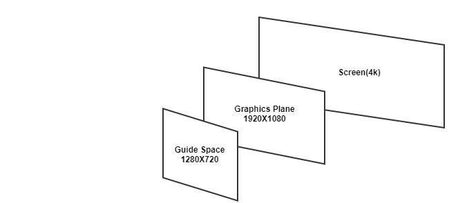
There are three coordinate spaces that the graphics developer needs to be aware of when working with graphics related code or when consulting with SOC developers on the proper implementation of various integration points.
NOTE: All coordinate systems all have an origin in the upper left corner and increase down and right.
Below is a hypothetical example of how the setup might look on a 4k display.
So in affect, the application drew a GUIDE in 1280x720 and it appeared perfectly scaled on a 3840x2160 TV.
There are a couple assumptions made at this point:
When the Output Resolution is considered to be standard definition, the Guide Plane is adjusted from the default 1280x720 to 640x480 with an exception for TrueSD mode.
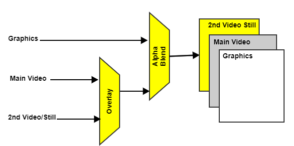
The graphics and video planes need to be arranged to form a cohesive display framework.
The order of planes are as follows from a user perspective :
Each video stream is assigned a video plane to render to. Video planes are at a lower z-order then the graphics plane. For full-screen video, the video plane is sized the same as the display output resolution. There are certain UI use cases where the video can be scaled down to a smaller size (e.g. PIP view). The video streams themselves will have their own resolution, often different from the plane size. The video pipeline will be configured to scale the video content to fit the plane, preserving the aspect-ratio of the video.
Since the graphics plane draws on top of the video plane, it is necessary for the graphics draw routine to draw transparency into the rectangle where video lives. We call this "hole punch". In the graphics tree, video will have a representative "video item" which when encountered during the graphics tree traversal, will handle doing the hole punch in graphics space. Once the graphics plane is scaled up to the display size, the rectangle of the hole punch will match the video plane.
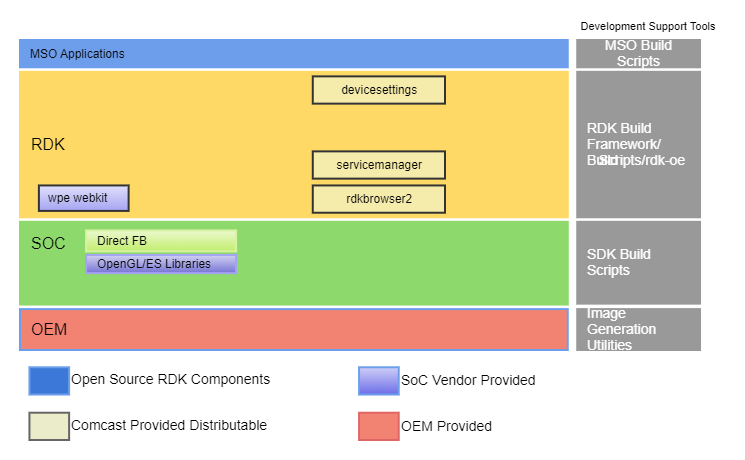
RDK uses Qt/WPE Webkit as the windowing framework and OpenGL/ES as the graphics engine, application rendering and user input framework. Creating an OpenGL context is quite a complex process & it varies between Operating Systems. Automatic OpenGL context creation has become a common feature of several user-interface libraries, including Qt and WPE.
Components related to RDK Graphics Subsystem